![]()
| 123DJ.COM Chicago DJ Equipment Online Superstore - PIONEER XDJ-R1 DIGITAL CONTROLLER AT OUR CHICAGO DJ EQUIPMENT STORE! |
 |
Pioneer XDJ-R1: Connections |
| Connecting the input/output terminals |
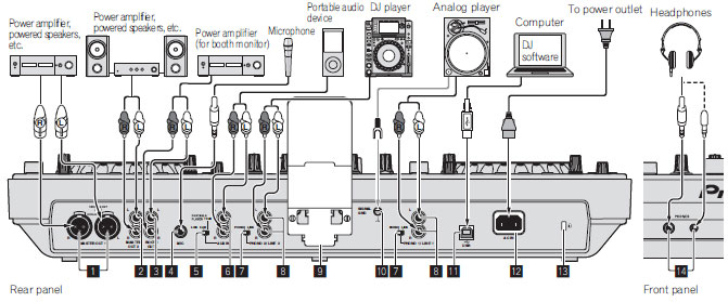 |
1. MASTER OUT 1 terminals Connect a power amplifier, powered speakers, etc., here. Be sure to use these as balanced outputs. Be careful not to acci- dentally insert the power cord of another unit. 2. MASTER OUT 2 terminals Connect a power amplifier, powered speakers, etc., here. 3. BOOTH output terminal This is an output terminal for a booth monitor. 4. MIC jack Connects a microphone here. 5. LINE, PORTABLE PLAYER selector switch Switch this according to the audio level input to the [AUX] terminals. 6. AUX IN terminals Connect a line level output device (such as a DJ player) or a device with a low gain (such as a portable audio player) here. Switch the terminals' input gain according to the connected device using the [LINE, PORTABLE PLAYER] selector switch on this unit's rear panel. 7. LINE, PHONO selector switch Switches the function of the [PHONO/LINE] terminals. 8. PHONO1/LINE1 and PHONO2/LINE2 terminals Connect a phono level output device (analog player (for MM car- tridges), etc.) or a line level output device (DJ player, etc.) here. Switch the terminals' function according to the connected device using the [LINE, PHONO] selector switch on this unit's rear panel. 9. Smartphone stand A mobile device can be set here. For instructions on mounting the smartphone stand, see Mounting the smartphone stand on page 4. 10. SIGNAL GND terminal Connects an analog player's ground wire here. This helps reduce noise when the analog player is connected. 11. USB terminal Connect to a computer. - A USB hub cannot be used. - To maintain performance, use with this unit and the computer connected directly using the included USB cable. 12. AC IN Connect this to a power outlet. Connect the power cord after all the connections between devices have been completed. Be sure to use the included power cord. 13. Kensington security slot 14. PHONES jacks Connect headphones here. Both stereo phone plugs (Ø 6.3 mm) and stereo mini phone plugs (Ø3.5 mm) can be used. |
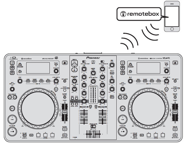
| Connecting by wireless LAN |
With this unit, a mobile device supporting wireless LAN connections can be connected directly without using router, etc., to hold DJ performances using the mobile device application (remotebox). This unit does not support wireless LAN connection via a router. |
 |
Setting the wireless LAN function's operation modeSet the wireless LAN function's operation mode before connecting this unit by wireless LAN. The buttons and controls below are used for making the wireless LAN function's operation mode settings and wireless LAN connection settings. |
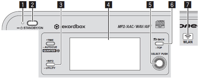 |
1. Press the [STANDBY/ON] button. Turn on the power of this unit. The [STANDBY/ON] indicator lights green. 2. Press the [INFO(UTILITY)] button for over 1 second. The [UTILITY] screen is displayed. 3. Turn the rotary selector, select [WLAN SETTING], then press the rotary selector. See page 25 for the list of [WLAN SETTING] items. 4. Turn the rotary selector, select [MODE], then press the rotary selector. 5. Turn the rotary selector, select the mode you want to set, then press the rotary selector.
6. When [APPLY CHANGES?] appears on the main unit display, turn the rotary selector to select [YES], then press the rotary selector. After this, make the settings for connection in the ENABLE mode. Making the wireless LAN connection settings in the ENABLE mode1. Press the [INFO(UTILITY)] button for over 1 second. 2. Turn the rotary selector, select [WLAN INFO], then press the rotary selector. 3. Turn the rotary selector, select [SSID], then press the rotary selector. Make a note of the [SSID] for future reference. The first 9 characters of the [SSID] are displayed. Turn the rotary selector to display the portion that is not initially displayed. 4. Press the [BACK(TOP)] button. Press to return to the previous screen. 5. Turn the rotary selector, select [PASSWORD], then press the rotary selector. Make a note of the [PASSWORD] for future reference. 6. From the wireless LAN connection settings on the mobile device or computer, display the connectable [SSID]s. See your device's operating instructions for instructions on searching for or displaying connectable [SSID]s. 7. On the mobile device or computer, select the [SSID] checked in step 3. 8. Input the password you made a note of in step 5. For safety, be sure to change the default password. We recommend changing the password periodically. Checking the current wireless LAN settings1. Press the [INFO(UTILITY)] button for over 1 second. The [UTILITY] screen is displayed. 2. Turn the rotary selector, select [WLAN INFO], then press the rotary selector. See page 24 for the list of [WLAN INFO] items. 3. Select the item you want to check, then press the rotary selector. The settings are displayed. When the [BACK(TOP)] button is pressed, the screen returns to the [WLAN INFO] screen. 4. Press the [INFO(UTILITY)] button. The [UTILITY] screen closes. |
Changing the SSID and password1. Press the [INFO(UTILITY)] button for over 1 second. The [UTILITY] screen is displayed 2. Turn the rotary selector, select [WLAN SETTING], then press the rotary selector. 3. Turn the rotary selector, select [NETWORK SETTING], then press the rotary selector. 4. Turn the rotary selector, input the [SSID], then press the rotary selector. 5. Turn the rotary selector and set the security type at [SECURITY]. [WEP64]: A 5-character password can be set.
6. Turn the rotary selector and set the password. 7. When [APPLY CHANGES?] appears on the main unit display, turn the rotary selector to select [YES], then press the rotary selector. 8. Press the [INFO(UTILITY)] button. The [UTILITY] screen closes. |
Phone: 312-846-6192 • Fax: 312-492-8949
Toll Free 1-800-856-8397
CONTACT US - BEAT A PRICE - GEAR RENTAL - TRACK YOUR PACKAGE - RETURNS / WARRANTY INFO
ABOUT US - SHIPPING INFO - PURCHASE ORDERS - CUSTOM INSTALLATION - TERMS


If you don't see it, it doesn't mean we don't have it. If you are interested in a certain product, but don't see it on our website, please call us or e-mail us!
*All products subject to available stock.
Copyright © 2014 by www.123DJ.com